"recharging" your patience. I like that, sounds better than "trying to defuse the bomb".
Screw clamp? Like a clamp holding the coupling together? Trying to dig up pics of mine but I don't remember a clamp around it. That sounds bad...
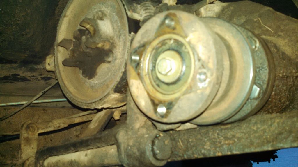
I removed mine because I thought the coupling was "bad". Lots of vibrations. Turns out it wasn't the coupling but the nut holding the mounting flange onto the transfer case was loose.
Then I moved the drive shaft to the other output to reduce some of the gawdawful noise from the transfer case. But the 724 drive shaft is shorter than the 715 drive shaft because of the coupling being in there. I took the old shaft and the shaft from the other output that used to go to the welder and had a new shaft made.
If you don't have the lever or linkages for that coupling... and can't use it.. to me, seems like it's just a liability.
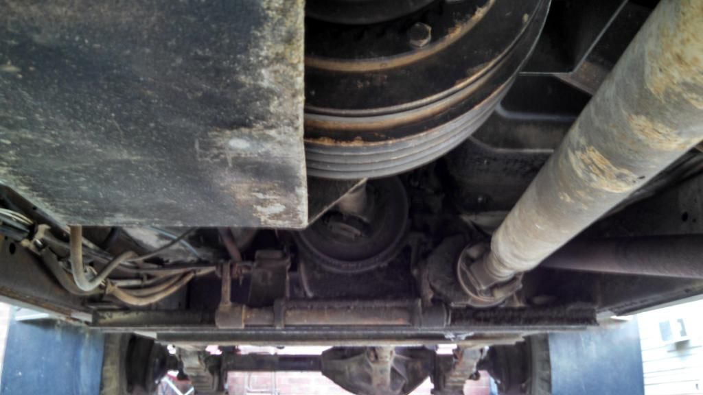
found pics.. from when I first got it and while removing the coupling.
Thought I had more, maybe I posted those on the Zoo and don't have them on photobucket..


Originally Posted by Don Cavey


 Reply With Quote


