Page 3 of 5 FirstFirst 12345 LastLast
Results 21 to 30 of 44

Thread: running dual charging systems 12V/24V

  1. #21
    Join Date
    Sep 2010
    Location
    Middleville, mi.
    Posts
    1,245

    Default

    Quote Originally Posted by Blitz View Post
    From another forum, on Yachts, in relation to using a 12 volt system off of a 24 volt charging system, and ""Sharing a Ground"" ( DC Voltage , 12 and 24 volt )

    Quote:

    In theory, yes, all "ground" busses would be tied together.

    But in practice, this creates a new hazard on the boat. By tying the 12 and 24 volt grounds together, you now create the hazard that you can have a short or other unintentional connection between the 12 V+ and 24V+ systems, putting 24V on the 12V system or creating a 12V loop in the 24V side.

    That might be a small hazard and worth ignoring in favor of having one common ground--but I'd check out the system with that thought in mind, and make doubly sure the two system positives were kept isolated from each other to make sure it couldn't happen.

    End Quote.
    I don't really see this as being a problem.

    If two positives "short" together on any system single or dual voltage, it is a problem.

    I agree it may be a bigger problem in a dual voltage system.

    Having any positive connecting to another positive seems unlikely to me. If all the wiring was installed properly to begin with and is not damaged somehow I don't see this as an issue.

  2. #22
    Join Date
    Aug 2013
    Location
    Palestine TEXAS
    Posts
    1,120

    Default

    Its always good to know two more more ways of skinning a cat.

    It seems it would be easier to just mount everything up, and use the body as a ground for everything, and for both voltages.

    Without this thread, and the questions that it has posed...
    and the answers that have been shared, I would Not have known this.

    I think we have all learned something. ( which is the point anyway )

    I dont have any more plans to install any more 12 volt appliances, and everything is pretty much done on my end.

    If I ever get another M 715, stock with 24 volts...
    I will probably consider using the body as a common ground.

    Out of an abundance of caution, and fear of meltdown for a frame up restore truck ( Thanks Gunny ), I'm glad its done and I honestly feel better knowing that I could have kept it all tied together, but isolated everything for safety overkill.

    I still dont have the theory solidified in my mind, and I still have some questions about it that are not really relevant here, but I still want to know.

    I will keep this in my mind and look on occasion for new info or other more detailed theory explanations.

    what is throwing me ( but does not apply to US ) is the NEG 24 volt leg and the Neg 12 volt leg... are negative voltages.

    not 0 volts.

    I dont know if that really matters in a worst case scenario, but those seem to be current carrying legs, with NEG voltages present...

    Not a 0 volt connection.

    Just trying to Grock the Theory, for my own understanding.

    For a military Truck, it seems we are good to go wither way.
    Now I know, from this Post.

    I guess the next logical step is researching Military Vehicle dual voltage systems, and how they work and are configured.

    I have learned a lot, looking this stuff up.. and on various subjects related to this.

    I will try to find the diagram of how to run 12 volt headlights off of a 24 volt system, without burning them out, and how to make one stay lit of the other does burn out, instead of both failing...

    I thought that was cool to know.

    Would not know that with out this discussion .

    here it is:
    More diagrams here and explanation:
    http://www.mcicoach.com/service-supp...serinfo07G.htm

    Last edited by Blitz; November 26th, 2014 at 11:43 AM.
    hostis est intra portas tuas

  3. #23
    Join Date
    Sep 2010
    Location
    Middleville, mi.
    Posts
    1,245

    Default

    Quote Originally Posted by Blitz View Post
    Its always good to know two more more ways of skinning a cat.

    More diagrams here and explanation:
    http://www.mcicoach.com/service-supp...serinfo07G.htm

    The problem with this diagram is that if one light does burn out you will be drawing from only one battery. That would be okay in a pinch but you would want to replace the burned out light as soon as practical.

    Also it doesn't say in that diagram but the wattage of both lamps should be the same.

    I am actually running my ignition coil in a similar fashion on my truck right now. I have two 12 volt coils run in series but I only have one coil actually connected to the distributor.

  4. #24
    Join Date
    Aug 2013
    Location
    Palestine TEXAS
    Posts
    1,120

    Default

    I remember you saying You had two coils, in one of Your posts.

    I had the 12 volt converter box already installed when i got the truck, and thats all that is run from it still.. the single 12 volt coil.
    This is also good to know, should the converter box fry one day.

    I did make a jumper wire, for just such an emergency...

    but once again... two more ways to Skin a Cat : ) .

    I do carry a spare coil, and this is an option .
    I guess I should throw in a mount in the spares box.


    For the 12 volt headlights,

    In a Pinch, and on the road...
    this could work well at a local auto parts store, with some female cannon connectors, some female blade connectors, 6 feet of 12 ga wire, and you could still be using the stock 24 volt switch.

    And back on the road...
    ( provided a circular headlight can still be found !! )

    I only have one spare 24 volt headlight bulb...

    Been needing to get more ... add it to the list.


    I'm wondering also , if you could run a set of auxiliary driving lights in this same configuration, but using the toggle switch supplied with the lights.

    Seems you would need to break two connections for both of them to ever shut off...
    Like with a DPST switch would probably be required, But that opens up some possibilities as well, for a permanent fixture.

    Just food for thought for now.

    I need some way to power My Pet Sharks Laser Beams.
    hostis est intra portas tuas

  5. #25
    Join Date
    Aug 2013
    Location
    Palestine TEXAS
    Posts
    1,120

    Default

    I Misspoke...

    Bullet connectors like this, fit the stock Packard connections well...

    I said cannon connectors...
    wrong word.

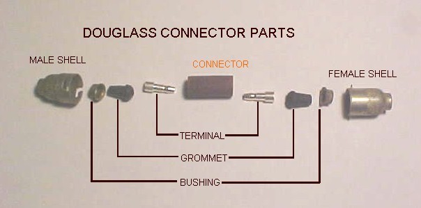
    Some of the 24 volt lights have the Douglass connectors too... worth checking out in advance.


    Bullet, standard crimp on:


    Packard:


    Last edited by Blitz; November 26th, 2014 at 11:19 PM.
    hostis est intra portas tuas

  6. #26
    Join Date
    Dec 2003
    Location
    Giddings, Texas
    Posts
    7,731

    Default

    Good info. TexasAggie, what year are you? 1990 myself. Whoop!
    Remember if you didn't build it you can't call it yours.

    6.2 powered M715, 5 M1009's, M416, 2 M101's, 2 M105's, 3 M35's, M1007 6.5 turbo Suburban project called Cowdog.

    https://www.youtube.com/channel/UCCz...HGkBCfhXZ5iuaw

  7. #27
    Join Date
    Sep 2010
    Location
    Middleville, mi.
    Posts
    1,245

    Default

    Quote Originally Posted by Blitz View Post
    Welcome to The Zone Texas Aggie,
    and Thank You for sharing in Your expertise .

    A 1 volt drop in DC is a pretty big drop.
    Just for clarification.

    The NEC dictates allowable voltage drop by percentage. High voltage and low voltage are treated different.

    In a high voltage (above 50 volts) feeder circuit the drop (or rise) can be no more than 3%. In a branch circuit the drop can be no more than 5%. A feeder circuit example would be a circuit starting at your main electrical panel and feeding a sub panel. A branch circuit example would be the circuit that powers lights in the kitchen.

    For low voltage the allowable voltage drop is 10%. That sounds like a lot but if you start at 12 volts and lose 10% you end at 10.8.

    So yes a 1 volt drop on 12 volts is substantial but a one volt drop on a 24 volt system is not so much.

  8. #28
    Join Date
    Sep 2010
    Location
    Middleville, mi.
    Posts
    1,245

    Default

    Quote Originally Posted by Blitz View Post

    what is throwing me ( but does not apply to US ) is the NEG 24 volt leg and the Neg 12 volt leg... are negative voltages.

    not 0 volts.

    I dont know if that really matters in a worst case scenario, but those seem to be current carrying legs, with NEG voltages present...

    Not a 0 volt connection.
    The easy way to think about a battery is it contains "potential" energy. There are two poles. The two poles reference each other. Without a "load" all you have is potential.

    As soon as you tie one side of a battery to the frame the entire frame shares a reference point to the remaining pole. It shares that potential.

    There were cars in the past that bonded the positive side of the system to the frame. That was called a positive ground. In that system the negative pole is the "hot".


    In the low voltage world we often bond the negative voltage to earth ground. We need to have a place to let the noise that gets into (or is generated by) the system, have a place to drain.

  9. #29
    Join Date
    Aug 2013
    Location
    Palestine TEXAS
    Posts
    1,120

    Default

    Its gonna take some time for the theory to sink into my head.

    In practical use, I got it down probably 85% + of the time, and with an over safety factor.
    both AC and DC.

    When You connect the 12 or 24 volt negative poles to EARTH Ground, NOW , to me thats a 0 voltage connection.
    In a Vehicle, we dont connect the neg poles to an earth ( as in Planet earth ) ground, so there seems to be a potential of 12 volts NEGATIVE or 24 volts Negative, on those lines.

    This is where I'm anticipating a problem...
    A 24 volt negative inducing current ( backflow? ) into a 12 volt only line, backwards basically.

    I'm sure its all been worked out, and those that "get it" get it.. and wrote the books...
    But it just has not solidified in my mind. ( remember its feeble and skewed )

    It will work out in time, and I appreciate you sharing the specific details, which are logged and ready for immediate future reference in my head.

    So a 24 volt NEGATIVE charge, cannot run backwards into a 12 volt system?

    Maybe I had too many plumbing courses, and Im thinking we need a backflow preventer, or one way check valve, or pressure compensating valve.

    Sorry to mix water and electricity here, but its just how I'm programmed.


    ok, Let me go back to the NEC. and low voltage (under 50 volts AC or DC)

    10.8 volts, from a TRANSFORMER.... ( AC to DC constant voltage )
    should be absolutely no problem for sizing wire and voltage drop.

    BUT.... BUT.... When we are using batteries, and have no constant AC power source to recharge them, or to keep the voltage constant...

    10.8 volts will be cooking and eating batteries, due to depth of discharge.

    Once again, this is why i go overkill, over safety and oversized wiring.

    The NEC does cover solar photovoltaic systems, to a small extent, mainly dealing with safety of structures.

    In practical "alternative energy" off the grid, backup or "portable systems" such as our Trucks... The NEC is pretty weak... just to be honest.

    The only time I've had an issue with deep battery 'draw down' on 12 volts is with inverters that have a preset ( non adjustable ) shut off point, of 11.5 volts.

    Some are settable to 10.5, but those LVD's are more $$, and its harder on the batteries in the long run. ( and not recommended to draw a battery down that far under load )

    The "reconnect" voltage can be as high as 13.4,( on a solar system ) to prevent fast cycling when the inverter shuts off and the battery 'springs back' to a higher voltage , when the load is removed.

    Standard reconnect is 12.5 to 12.7, but the 13.4 on solar, ensures the solar panel is charging fully and the battery is topped off completely, before the inverter will kick back on service.


    All I'm saying here, is that the NEC seems to allow for 10.8 volts in voltage drop,( on 12.5 volts DC) which I would consider unacceptable while wiring a battery backup system, and I sure would go the next wire size bigger or even three.

    Some of My stuff is wired with MCM cable, and at minimum, 2/0 for battery interconnects, which are only about 12 inches long each.
    I believe in Big wire..
    and most of the stuff I do is for ME, so I dont have to justify the cost to a client, or explain the safety and efficiency factors.


    Someday, I will run across some reasonable 24 volt inverters, and maybe a model that is stackable in pairs, to get 240 V AC out. ( for a 3 hp Fire pump )

    More big bucks.
    I dont think I'll find one at a wrecking yard anytime soon.

    More for the list.
    and bigger welding wire , and more anderson SB connectors while I'm at it.

    I just need to win the lottery, or inherit a copper mine.

    I guess All I'm really saying is,

    I tend to go overkill, always, in wire size, GFCI protection, Over voltage protection, weatherproofing, conduit size and quality of cable.

    Even on a Paying Job, where I could get by with "code", i just always overkill it.

    Deep Cycle batteries are expensive.
    A Lot of alternative energy systems want the batteries shut off at 11.7 volts, just to save them.

    So, one real question...

    Can 24 volts on the negative side"backfeed" into the 12 volt circuits ?

    And last thing... corrosion ????????
    will this induce a dielectric or galvanic corrosive force into the appliances, such as lights ?

    I know we are mixing theaters here....
    AC,
    household wiring,
    Earth Ground 0 volts
    floating ground with a negative voltage potential...
    DC voltage
    and dual Dc voltage

    not to mention input power sources, and their service rating.

    Its all a "profession", and I can sure see why : )
    Last edited by Blitz; November 27th, 2014 at 10:36 AM.
    hostis est intra portas tuas

  10. #30
    Join Date
    Sep 2010
    Location
    Middleville, mi.
    Posts
    1,245

    Default

    Quote Originally Posted by Blitz View Post

    So a 24 volt NEGATIVE charge, cannot run backwards into a 12 volt system?
    Short answer...No.

    Think about two 12 volt batteries wired in series. What are you doing when you connect them in series? How is it that the positive of the first battery isn't shorted by the negative of the second battery? Because each battery only sees its own potential. But that connection between the batteries is a reference point they both share.

    This is strictly an anecdotal explanation...

    Electrons don't flow from negative to negative.

    If you were to bond the negatives of a 12 volt and a 24 volt system and then put a meter between the 12 volt positive and 24 volt positive what reading would you get?

Posting Permissions

  • You may not post new threads
  • You may not post replies
  • You may not post attachments
  • You may not edit your posts
  •  


Site Upgrade, Design Modifications & Administrative Support by:
Palm River Enterprises LLC, IT Solutions
President: Tom King, User ID=teking
This site is owned and operated by:
M715 Zone, LLC
President: Jon Schmidt, User ID=brute4c


If you have any suggestions, comments, problems or questions, contact:  brute4c@m715zone.com
Use of this site means you understand and agree to our TERMS OF USE

Copyright Notice:
This web site is subject to the protection of the copyright laws of the United States and other countries. Except for Personal Use Only, you may not modify, copy, distribute, transmit, display, perform, reproduce, publish, license, create derivative works from, transfer, or sell any information obtained from any part of the M715 Zone website without the prior written permission of M715 Zone, LLC. Written permission can only be obtained by contacting brute4c@m715zone.com

Copyright 1998-2024