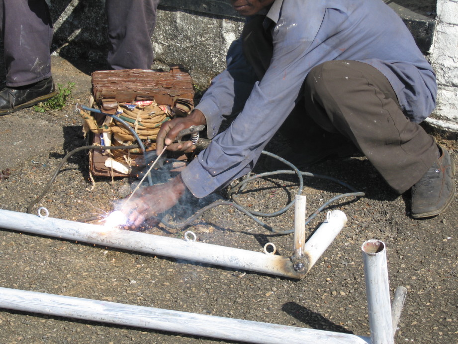
I just finished my welder for the truck. I made it out of an alternator and set it up with a bracket on the engine as a separate alternator.
here is a picture of the control box.
The panel meters are for voltage into the field, the voltage output of the alternator which can exceed 140 volts I am told, and the amperage out. You really dont need anything but the voltage out, but I thought it looked cool and was curious about the amperage out reading. The voltage in, will now be a fixed 12 volts because of me not using the variable voltage input I was planning on from the start of the project. you would need this part of the circuit if you were to use a smaller engine or use a 220 volt motor to drive the alternator.
I have it up and running at least. I still have to put on my vernier motor control and do some last minute work on the panel meters. I had some issues with everything so it took more time than expected to debug this one. The alternator I was using for this was set up for an external regulator so I thought it would be a plug and play thing, but after the truck stalled because the alternator was smoking, I took the alternator apart and found that the factory still places a diode inside for some reason or annother, and that diode shorted the output to ground causing the alt to put 200 amps directly to ground. I chucked the diode and everything is good now.
Just because I could, I over complicated my welder with a bunch of things that were not really needed. I have simplified it greatly by getting rid of the variable voltage input for the field. The reason for this is that you can still vary the engine speed to get different voltages out of the alt. You really dont need or want the ability to adjust the input voltage because you would want your engine to be at the lowest RPM you can. For this reason, I am just putting in a full 12 volts into the alternators field. I have found that some if not all of the professional welders use a open circuit voltage of 38 volts. the reason for this, is two fold. To be safe for the public, you have to keep the voltage below 50 volts ( considered low voltage by the UL and therefore no need for extra safety measures) the other reason is just because it allows you to strike an arc very easily and welds very nicely, no need for higher voltage.
An alternator welder is so easy to make, anyone can do it. If fact the most dificult part of the whole project, was to build the bracket for the engine to mount the alternator. I guess if anyone is interested, I can post some wiring diagrams or links that I thought were helpfull. I have found a lot of bad information out there on alternator welders. I am amazed at how easy this is to make. I think I am going to make one of these for each of my Jeeps, since it is cheap and easy.
In a nut shell, this is what you need to do for the basic unit.
Take the alternator apart and remove the regulator and the diode from the case then reassemble. (If you are using a GM alternator) for a Ford or Chrysler most have external which requires no mods or maybe just removing a diode inside the case.
connect the Bat + on the back of the alternator to your welder stinger lead. ( this is called reverse polarity, but is absolutely necessary because to weld on your own vehicle, you need it. To weld on someone elses vehicle you could reverse them if you wanted.)
Connect the ground terminal on the alt to the ground lead.
run battery power through a 20 amp fuse then to a toggle switch and from the other side of the switch to the field terminal of the alternator. ( this gives full power to the alternator and will give you the alternators max output.
Make some way for you to adjust the engines RPM. This could be a professional vernier cable or just a 10 speed bicycle shifter and cable. On my truck, Idle just happens to be 38.7 volts.
This is the most basic setup, but you can add a couple extra things that make it even better.
add a DC volt meter to this by connecting one lead of the voltmeter to each of the connections that your welder leads go to. ( this allows you to monitor the open circuit voltage and adjust your engines RPMs to the correct 38 volts or so, and it also will allow you to adjust the engines RPMs to give you 120 volts output.) If you have a tach, you could also measure the output with a hand held volt meter, and then see what RPM you need to get that voltage out. 2100 rpms = 38 volts so run it up to 2100 RPMs and weld. I bought mine from Ebay for about 10 bucks and is a cool blue LED panel meter. I would not recommend this one if your box will be under the hood though. water resistent is best for under the hood.
add a 120 volt outlet to run power tools. Connect the gold terminal to the + stinger and the silver terminal to the - or ground. ( anything with brushes for the motor and does not have a variable trigger. Just run your RPMs up until the meter reads 110-120 volts and plug it in. ( I need to caution you though, this will also give you 120 volts at the welding leads, which can be dangerous if not handled correctly.) I have made my welding leads with quick disconnects so I can just disconnect them when I rev up the engine for the 120 volt power.
You can use this as a power source to TIG weld also, or add a few parts and make it run a home made MIG welder.
I have noticed that the alternator gets very hot even after one welding rod is used. I may add annother diode rectifyer to the back of the alternator I have, just to make it easier on the diodes. sometimes you can stack these so that you can divide the amperage load between the rectifyers. If you have questions, just ask.


 Reply With Quote


