Results 1 to 7 of 7

Thread: Winch Mounting

  1. #1
    Join Date
    Dec 2003
    Location
    Giddings, Texas
    Posts
    7,732

    Default Winch Mounting

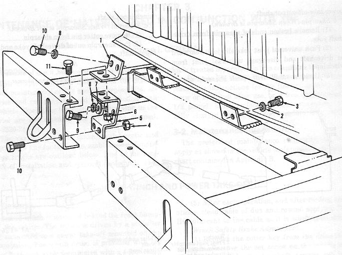
    We are finally done picking the engine up and down in Pistolnut's truck. So, now we can mount the winch. We have all the pieces along with the fasteners. Sitting in a pile in the bed. I have the one exploded view I can find in the manuals as a map. But, I can't remember what order we took it apart 2 years ago and I have all different students from them as well.

    Anybody out there care to recommend an order to putting the parts on the truck that works? Thanks.
    Remember if you didn't build it you can't call it yours.

    6.2 powered M715, 5 M1009's, M416, 2 M101's, 2 M105's, 3 M35's, M1007 6.5 turbo Suburban project called Cowdog.

    https://www.youtube.com/channel/UCCz...HGkBCfhXZ5iuaw

  2. #2
    Join Date
    Sep 1998
    Location
    North Central Wisconsin
    Posts
    11,531

    Default

    The manuals list Assembly, in the 34, and Installaion, in the 20...heres both:

    Assembly;
    20-9. Reassembly.

    a. Slide shifter handle (32) on shifter shaft (40) and secure shifter handle to shifter shaft with shaft set screw (29).
    b. Position shifter fork in clutch housing (24) and install shifter shaft assembly (40).
    c. Aline holes in shifter fork (37) and shifter shaft (40) and install shaft key (33).
    d. Install worm gear keys (55) on clutch drum shaft (46) and press worm gear (4) on the clutch drum shaft (46).
    e. Slide thrust ring (45) onto drum shaft (46) and install clutch drum shaft (46) in worm housing (24).
    f. Slide cable drum (16) on clutch drum shaft (46).
    g. Install thrust ring (45) and ciutch keys (19, 47) on clutch drum shaft (46).
    h. Install clutch (21) on clutch drum shaft (46) and engage clutch keys (19, 47) to clutch (21).
    i. Guide shifter fork (37) on groove of clutch (21) and clutch housing (24) on clutch drum shaft (46).
    j. Position drag brake screw (42) and fasten with cap nuts.
    k. Position the two base angle brackets (49) on the worm housing (5) and the clutch housing (24) and secure with eight cap screws and lock washers.
    1. Position worm key (64) to worm shaft (65) and press worm (66) in place on worm shaft (65).
    m. Position bearing spacer (67) and bearing cone (68) on worm shaft (65) and slide, as in assembly, in the worm housing (5).
    n. Press bearing cup (6) in front bearing container (10) and position new gaskets (9) and front bearing container (10) on worm housing (5) and secure with four mounting cap screws (73) and lock washers (72).
    o. Position seal (8) and bearing cup (6) in rear bearing retainer (10).
    p. Position new gasket (9), rear bearing container (10) and worm brake housing (12) to worm housing (5) and secure with four mounting cap screws and lock washers.
    q. Adjust end-play of wormshaft to allow for 1/64 to 1/32-inch.
    r. Position drive key on work shaft and install driver sleeve.

    NOTE
    Be sure drive key is alined to keyway in drive sleeve.

    Associated illustration for above:

    ---------------------------------------------------------------------------------
    Installation/Mounting:

    3-7. Installation.

    a. Driveshaft and Universal Joints. (Fig 3-1)
    (1) Slide driveshaft on power take-off output shaft. Install bolts, lock washer and nut which secures driveshaft to power take-off output shaft. Tighten securely.
    (2) Position driveshaft to winch input shaft and slide slip joint yoke forward.
    (3) Line up holes and install shearpin through universal joint yoke and winch input shaft.
    (4) Install cotter pin in shearpin.
    b. Shearpin.
    (1) Aline holes in winch input shaft and drive-shaft yoke.
    (2) Insert shearpin through universal joint yoke and power take-off output shaft.
    (3) Install cotter pin in shearpin.
    c. Winch Cable and Chain.
    (1) Apply a thin film of engine oil to winch drum surface.
    (2) Insert cable through winch rollers and around the drum at the rear.
    (3) Insert cable through hole in drum and secure with setscrew.
    (4) Wind cable under load, applying CW-11C lubricant to the cable as it winds on drum. Refer to paragraph 3-4c for method of applying CW-11C lubricant.
    d. Winch and Mounting Brackets. (Fig 3-2)
    (1) Position rear mounting bracket to frame assembly; install bolts, nuts and lock washers and tighten.
    (2) Install front brackets, bolts and lock washers into winch worm gear housing outer bolt holes, and tighten.
    (3) Support winch on jack or other suitable lifting device and raise into position.
    (4) Install six bolts and lock washers and secure rear bracket and winch assembly. Tighten bolts securely.
    (5) Install eight bolts, lock washers and nuts through front brackets and front bumpers. Tighten all eight attaching bolts. Install bolts, nuts and lock washers securing side rail extensions to frame. Tighten bolts securely.
    (6) Remove jack or lifting device.
    (7) Connect winch driveshaft as described in (a) above.

    Figure 3-1


    Figure 3-2

  3. #3
    Join Date
    Dec 2003
    Location
    Giddings, Texas
    Posts
    7,732

    Default

    Thanks Jon. I guess I was looking for pictures too much instead of reading.
    Remember if you didn't build it you can't call it yours.

    6.2 powered M715, 5 M1009's, M416, 2 M101's, 2 M105's, 3 M35's, M1007 6.5 turbo Suburban project called Cowdog.

    https://www.youtube.com/channel/UCCz...HGkBCfhXZ5iuaw

  4. #4
    Join Date
    Sep 1998
    Location
    North Central Wisconsin
    Posts
    11,531

    Default

    I hope it does the trick...I have never worked on a winch on these trucks...wish, but never been there...so I cant say how good the list above is...

  5. #5

    Default

    Tim, the bar and side brackets that go against the frame are NO FUN to get lined up. Please let someone work on that that has patience.
    "We are here for the meeting!"

  6. #6
    Join Date
    Dec 2003
    Location
    Giddings, Texas
    Posts
    7,732

    Default

    I remember the student that took it apart did not have patience. The one assigned to it now has plenty. I am having him piece everything together in the bed with the proper fasteners and all. We have already figured out the case halves are too close together after the winch rebuild a year or so ago. Which is a good thing to figure out now instead of when the winch is hanging from a hook.
    Remember if you didn't build it you can't call it yours.

    6.2 powered M715, 5 M1009's, M416, 2 M101's, 2 M105's, 3 M35's, M1007 6.5 turbo Suburban project called Cowdog.

    https://www.youtube.com/channel/UCCz...HGkBCfhXZ5iuaw

  7. #7
    Join Date
    Sep 1998
    Location
    North Central Wisconsin
    Posts
    11,531

    Default

    Might be a good idea to post what works and any problems...since this seems to be something of a blind spot...

Similar Threads

  1. Show me your winch (BUILT) winch bumpers
    By bluesman2a in forum Modified Tech
    Replies: 26
    Last Post: June 21st, 2009, 01:45 PM
  2. looking for winch mounting pics
    By Duane in forum Stock Tech
    Replies: 5
    Last Post: February 10th, 2009, 08:06 AM
  3. Div Np 205 mounting
    By tngreenmachine in forum Modified Tech
    Replies: 23
    Last Post: April 27th, 2007, 11:56 AM
  4. winch drive bracket mounting on M-715
    By bigkev143 in forum Stock Tech
    Replies: 1
    Last Post: January 23rd, 2007, 02:17 PM
  5. Needed: Winch frame bracket mounting pic.
    By teking in forum Open Discussion Archives
    Replies: 6
    Last Post: January 27th, 2004, 09:59 PM

Posting Permissions

  • You may not post new threads
  • You may not post replies
  • You may not post attachments
  • You may not edit your posts
  •  


Site Upgrade, Design Modifications & Administrative Support by:
Palm River Enterprises LLC, IT Solutions
President: Tom King, User ID=teking
This site is owned and operated by:
M715 Zone, LLC
President: Jon Schmidt, User ID=brute4c


If you have any suggestions, comments, problems or questions, contact:  brute4c@m715zone.com
Use of this site means you understand and agree to our TERMS OF USE

Copyright Notice:
This web site is subject to the protection of the copyright laws of the United States and other countries. Except for Personal Use Only, you may not modify, copy, distribute, transmit, display, perform, reproduce, publish, license, create derivative works from, transfer, or sell any information obtained from any part of the M715 Zone website without the prior written permission of M715 Zone, LLC. Written permission can only be obtained by contacting brute4c@m715zone.com

Copyright 1998-2024